1 项目目标
利用定时器产生周期为1ms的中断,作为系统时基。并在数码管上显示开机时间(分辨率为0.1秒);同时实现LED4、LED5、LED6和LED7分别以300ms、220ms、450ms和700ms为周期闪烁。
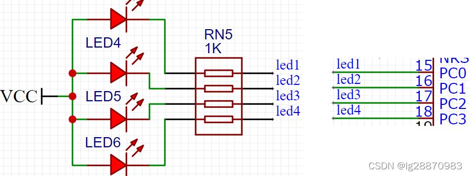
2 硬件电路
3 中断系统
3.1 什么是中断
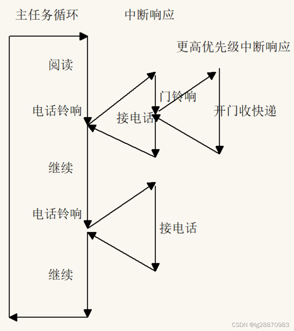
中断就是正常执行的工作被一些突发的事件所打断。比如我们在看书,电话铃响了。看书是我们正在进行的事情,电话铃响就是一个突发事件。电话铃响了,我们就会停下手头的事情,去接电话。接电话这个动作,就是对这个中断事件的响应。电话接完了,接着看书,回归正常工作。
中断这种工作机制,主要是为提高效率,另外一种方式叫查询式。还是以接电话为例,比如手机处于免打扰状态,电话来的时候没有铃声提醒。如果我们不想漏过电话,只能一会儿抽空看一眼手机,有没有电话打进来。这种工作方式相对中断式工作效率偏低。
中断方式和查询方式相比,好处在于加快了响应速度,一旦发生某个事件,可以快速响应。提高了系统的实时性能。
中断方式有个问题是,如何保证中断响应完成后能无缝继续刚刚被打断的工作。当然人没有这个问题,单片机内部只有一个CPU,就需要专门设计的方式来保证这种工作方式的正确性。
AT32的中断系统非常强大,所有的外设几乎都可以工作于中断方式。
3.2 中断系统的几个概念
中断源 即中断是来源于哪个外设的哪个事件,比如定时器时间到、外部引脚电生了电平跳变、UART收到了一个数据等等
中断请求 当有事件发生时,中断系统向CPU发出执行中断请求
中断响应 当发生了一个中断事件时,需要去做的事情,就是对这个中断的响应
中断优先级 中断事件可以打断当前的正在执行的程序,如果两个中断同时发生了,先去响应哪一个呢?为解决这个问题,给中断定义不同的优先级,首先响应优先级高的中断。如果两个相同优先级的中断同时来了,怎么办?简单点,按事先规定的顺序(就像我们经常说的按姓氏笔画,排名不分先后)。
3.3 中断的执行过程
4 Timer定时中断
AT32F407VGT6有14个寄存器,功能对比如下:
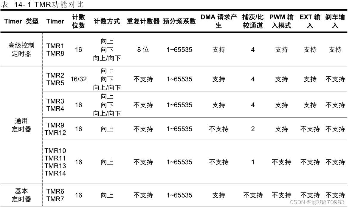
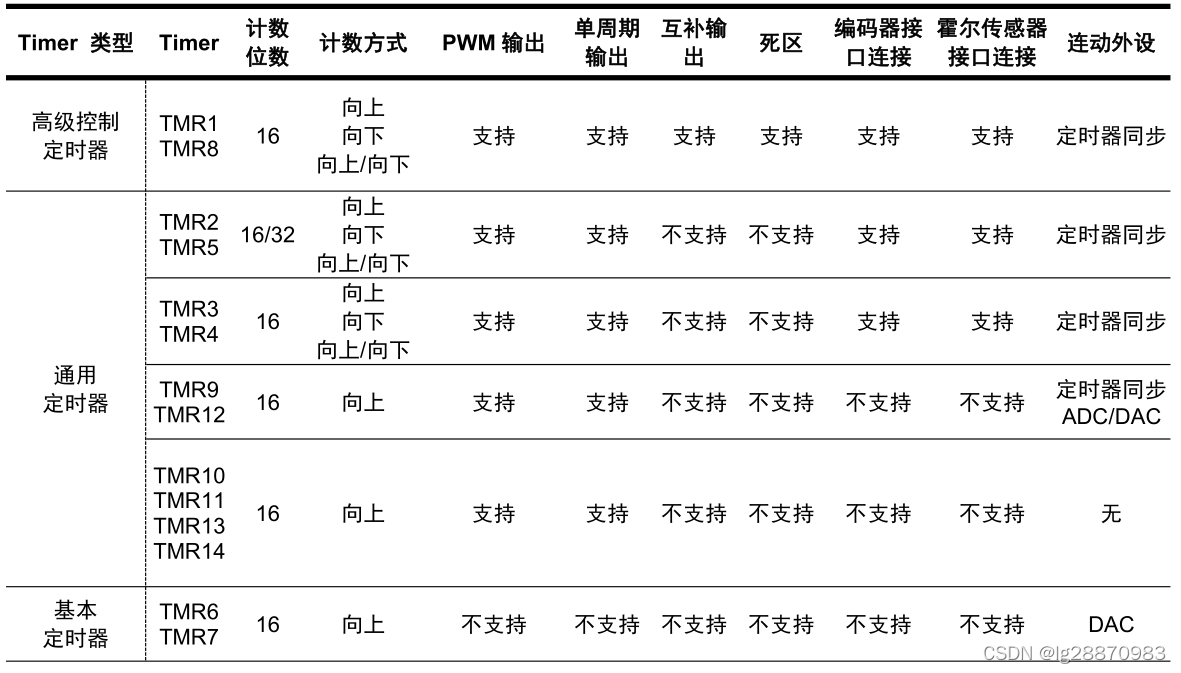
本例采用基本定时器TMR6,作为1ms的时基定时器。
4.1 AT32F407系统时钟系统
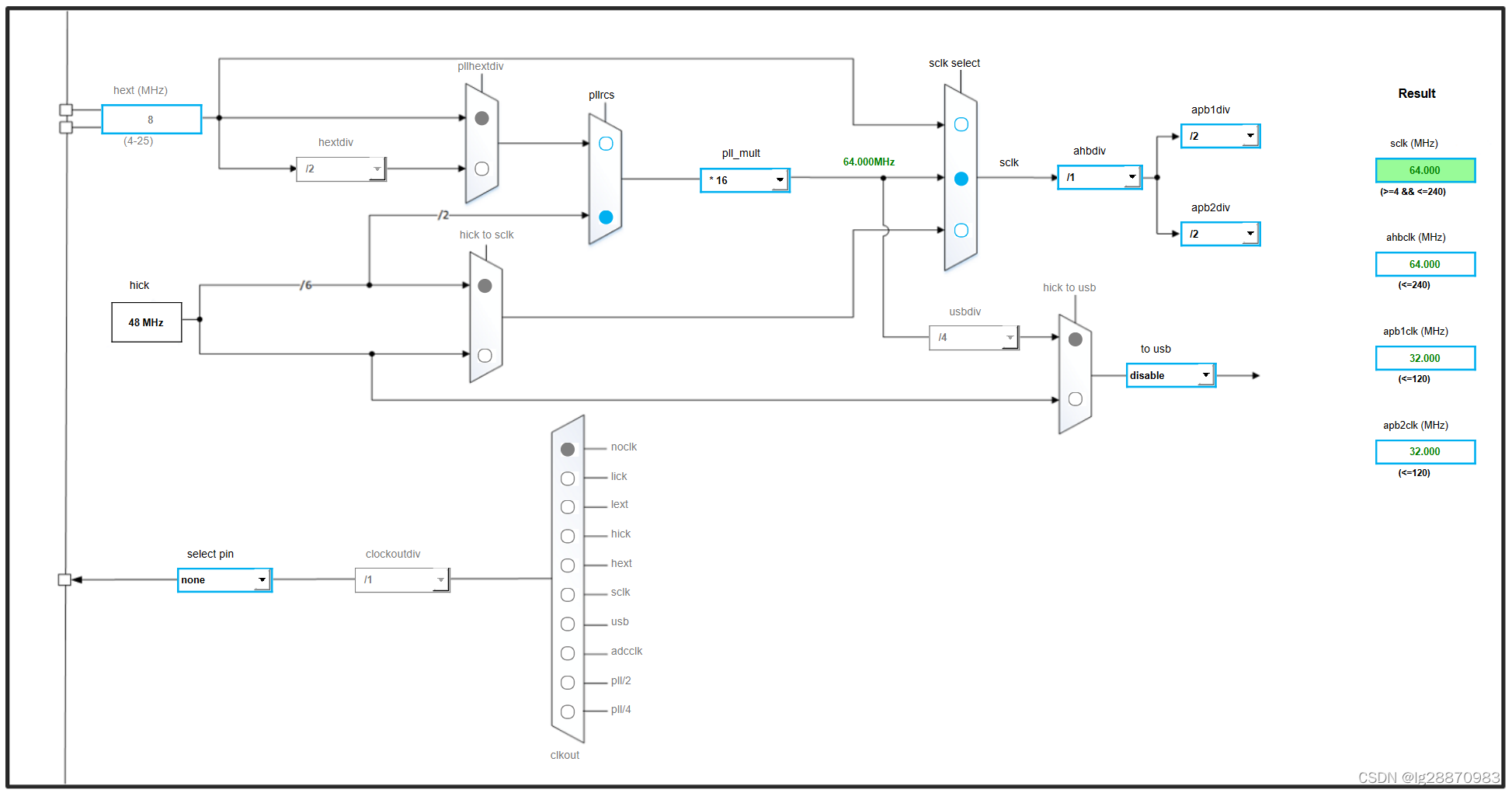
本例采用内部RC振荡器时钟,然后通过PLL(锁相环)倍频后作为系统时钟。可以在雅特力官网下载AT32_New_Clock_Configuration工具自动生成时钟配置代码。本例系统时钟为64MH,APB1、APB2的分频系数为2,其频率都为32MHz。
- /**
- * @brief system clock config program
- * @note the system clock is configured as follow:
- * system clock = hick / 12 * pll_mult
- * system clock source = pll (hick)
- * sclk = 64000000
- * ahbdiv = 1
- * ahbclk = 64000000
- * apb1div = 2
- * apb1clk = 32000000
- * apb2div = 2
- * apb2clk = 32000000
- * pll_mult = 16
- * pll_range = LE72MHZ (less than 72 mhz or equal to 72 mhz)
- * @param none
- * @retval none
- */
- void system_clock_config(void)
- {
- /* reset crm */
- crm_reset();
-
- /* enable hick */
- crm_clock_source_enable(CRM_CLOCK_SOURCE_HICK, TRUE);
-
- /* wait till hick is ready */
- while(crm_flag_get(CRM_HICK_STABLE_FLAG) != SET)
- {
- }
-
-
- /* config pll clock resource */
- crm_pll_config(CRM_PLL_SOURCE_HICK, CRM_PLL_MULT_16, CRM_PLL_OUTPUT_RANGE_LE72MHZ);
-
- /* enable pll */
- crm_clock_source_enable(CRM_CLOCK_SOURCE_PLL, TRUE);
-
- /* wait till pll is ready */
- while(crm_flag_get(CRM_PLL_STABLE_FLAG) != SET)
- {
- }
-
-
- /* select pll as system clock source */
- crm_sysclk_switch(CRM_SCLK_PLL);
-
- /* wait till pll is used as system clock source */
- while(crm_sysclk_switch_status_get() != CRM_SCLK_PLL)
- {
- }
-
-
- /* config ahbclk */
- crm_ahb_div_set(CRM_AHB_DIV_1);
-
- /* config apb2clk */
- crm_apb2_div_set(CRM_APB2_DIV_2);
-
- /* config apb1clk */
- crm_apb1_div_set(CRM_APB1_DIV_2);
-
- /* update system_core_clock global variable */
- system_core_clock_update();
- }
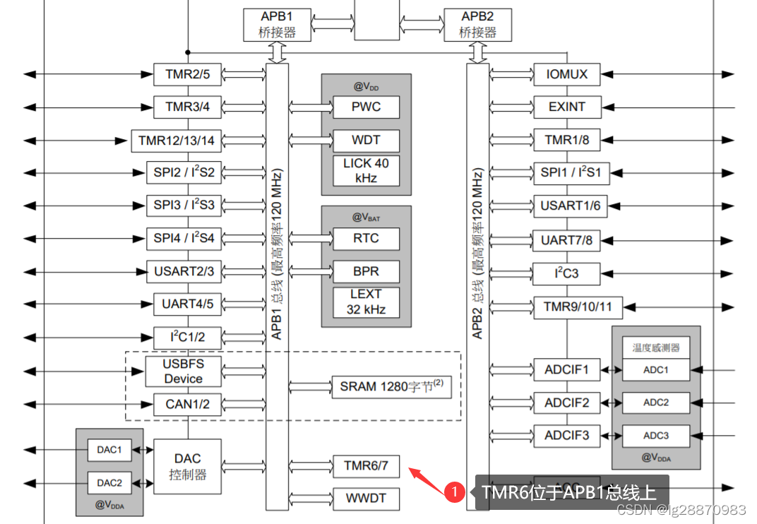
定时器使用 APB1 总线时钟,特别地,当 APB 预分频系数是 1 时,定时器的时钟频率等于 APB1 的时钟频率;当 APB 预分频系数不为 1 时,定时器的时钟频率等于 APB1 时钟频率的 2 倍。本例APB2分频系统为2,所以TMR6的时钟频率为 32*2 = 64MHz。
4.2 TMR6定时器溢出中断工作方式
基本定时器仅提供向上计数模式。其内部拥有一个 16 位计数器,计数器的值可由周期寄存器(TMRx_PR)载入。周期寄存器寄存器的值为16时,计数器如下图方式工作。
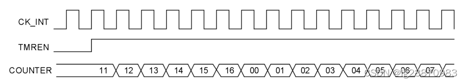
向上计数模式中,当计数值达到 TMRx_PR 值时,重新从 0 向上计数,计数器上溢并产生溢出事件,同时 OVFIF 位置 1。
定时器工作时钟为64MHz,将分频系数设置为64000(注意分频系统最大为65536),计数的输入时钟周期为1us,周期设置为1000,则得到1ms。需要注意的时,实际设置分频系数和周期寄存器时,都需要将计算值减1。
- /**
- * TMR6初始化 周期为1ms
- */
- void tmr6_init(void)
- {
- /* enable tmr14 clock */
- crm_periph_clock_enable(CRM_TMR6_PERIPH_CLOCK, TRUE);
-
- /* 64000000/64/1000 = 1000Hz*/
- tmr_base_init(TMR6, 1000 - 1, 64 - 1);
- tmr_cnt_dir_set(TMR6, TMR_COUNT_UP);
-
- /* overflow interrupt enable */
- tmr_interrupt_enable(TMR6, TMR_OVF_INT, TRUE);
-
- /* tmr1 overflow interrupt nvic init */
- nvic_priority_group_config(NVIC_PRIORITY_GROUP_4);
- nvic_irq_enable(TMR6_GLOBAL_IRQn, 0, 0);
-
- /* enable tmr1 */
- tmr_counter_enable(TMR6, TRUE);
- }
4.3 中断响应函数
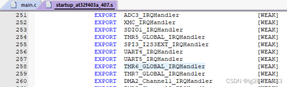
中断响应函数每次定时器溢出,也就是每隔1ms,就会被调用一次。我们在这儿进行数码管显示刷新,全局变量gSysTick加1。退出中断之前,要把中断标志清除,否则中断函数会被不停调用。所有中断响应函数名称在startup_at32f403a_407.s中已经预定义。
- void TMR6_GLOBAL_IRQHandler(void)
- {
- if(tmr_flag_get(TMR6, TMR_OVF_FLAG) != RESET)
- {
- gSysTick++;
- display_scan();
- tmr_flag_clear(TMR6, TMR_OVF_FLAG);
- }
- }
4.4 独立控制4个LED的方法
全局变量gSysTick每隔1ms会加1,作为系统的时基,它的值就是系统开始运行到现在毫秒数。我们可以利用这个变量作为控制4个LED的闪烁的基准时间。由于4个LED闪烁周期都不相同,我们定义4个函数分别控制LED4-LED7。下面代码以LED4为例来说明。
- void led4_ctrl(void)
- {
- static uint32_t tick = 0;
- if(gSysTick - tick >= 300/2){
- tick = gSysTick;
- if(gpio_output_data_bit_read(GPIOC, GPIO_PINS_0)==SET)
- gpio_bits_reset(GPIOC, GPIO_PINS_0);
- else
- gpio_bits_set(GPIOC, GPIO_PINS_0);
- }
- }
static表示这个变量会持续存在,不会在函数退出时被销毁。
5 参考程序
main.c
- #include "at32f403a_407_conf.h"
-
- #include "display.h"
-
- uint32_t gSysTick = 0;
-
- /**
- * @brief system clock config program
- * @note the system clock is configured as follow:
- * system clock = hick / 12 * pll_mult
- * system clock source = pll (hick)
- * sclk = 64000000
- * ahbdiv = 1
- * ahbclk = 64000000
- * apb1div = 2
- * apb1clk = 32000000
- * apb2div = 2
- * apb2clk = 32000000
- * pll_mult = 16
- * pll_range = LE72MHZ (less than 72 mhz or equal to 72 mhz)
- * @param none
- * @retval none
- */
- void system_clock_config(void)
- {
- /* reset crm */
- crm_reset();
-
- /* enable hick */
- crm_clock_source_enable(CRM_CLOCK_SOURCE_HICK, TRUE);
- /* wait till hick is ready */
- while(crm_flag_get(CRM_HICK_STABLE_FLAG) != SET)
- {
- }
- /* config pll clock resource */
- crm_pll_config(CRM_PLL_SOURCE_HICK, CRM_PLL_MULT_16, CRM_PLL_OUTPUT_RANGE_LE72MHZ);
- /* enable pll */
- crm_clock_source_enable(CRM_CLOCK_SOURCE_PLL, TRUE);
- /* wait till pll is ready */
- while(crm_flag_get(CRM_PLL_STABLE_FLAG) != SET)
- {
- }
- /* select pll as system clock source */
- crm_sysclk_switch(CRM_SCLK_PLL);
-
- /* wait till pll is used as system clock source */
- while(crm_sysclk_switch_status_get() != CRM_SCLK_PLL)
- {
- }
- /* config ahbclk */
- crm_ahb_div_set(CRM_AHB_DIV_1);
- /* config apb2clk */
- crm_apb2_div_set(CRM_APB2_DIV_2);
- /* config apb1clk */
- crm_apb1_div_set(CRM_APB1_DIV_2);
-
- /* update system_core_clock global variable */
- system_core_clock_update();
- }
-
- /**
- * TMR6初始化 周期为1ms
- */
- void tmr6_init(void)
- {
- /* enable tmr14 clock */
- crm_periph_clock_enable(CRM_TMR6_PERIPH_CLOCK, TRUE);
-
- /* 64000000/64/1000 = 1000Hz*/
- tmr_base_init(TMR6, 1000 - 1, 64 - 1);
- tmr_cnt_dir_set(TMR6, TMR_COUNT_UP);
-
- /* overflow interrupt enable */
- tmr_interrupt_enable(TMR6, TMR_OVF_INT, TRUE);
-
- /* tmr1 overflow interrupt nvic init */
- nvic_priority_group_config(NVIC_PRIORITY_GROUP_4);
- nvic_irq_enable(TMR6_GLOBAL_IRQn, 0, 0);
-
- /* enable tmr1 */
- tmr_counter_enable(TMR6, TRUE);
- }
-
- /**
- * TMR6中断响应函数
- */
- void TMR6_GLOBAL_IRQHandler(void)
- {
- if(tmr_flag_get(TMR6, TMR_OVF_FLAG) != RESET)
- {
- gSysTick++;
- display_scan();
- tmr_flag_clear(TMR6, TMR_OVF_FLAG);
- }
- }
-
- /**
- * 显示gSysTick
- */
- void display_tickcount(void)
- {
- static uint32_t tick = 0;
- if(gSysTick - tick >= 100){
- display_dec_int(gSysTick/100);
- tick = gSysTick;
- }
- }
-
- /**
- * LED闪烁控制
- */
- void led_gpio_init(void)
- {
- //打开GPIO时钟
- crm_periph_clock_enable(CRM_GPIOC_PERIPH_CLOCK, TRUE);
-
- //配置PD2~PD5, PE0~PE7为输出
- gpio_init_type gpio_init_struct;
-
- gpio_init_struct.gpio_pins = GPIO_PINS_0 | GPIO_PINS_1 | GPIO_PINS_2 | GPIO_PINS_3;
- gpio_init_struct.gpio_mode = GPIO_MODE_OUTPUT;
- gpio_init_struct.gpio_out_type = GPIO_OUTPUT_PUSH_PULL;
- gpio_init_struct.gpio_pull = GPIO_PULL_NONE;
- gpio_init_struct.gpio_drive_strength = GPIO_DRIVE_STRENGTH_STRONGER;
-
- gpio_init(GPIOC, &gpio_init_struct);
- }
- void led4_ctrl(void)
- {
- static uint32_t tick = 0;
- if(gSysTick - tick >= 300/2){
- tick = gSysTick;
- if(gpio_output_data_bit_read(GPIOC, GPIO_PINS_0)==SET)
- gpio_bits_reset(GPIOC, GPIO_PINS_0);
- else
- gpio_bits_set(GPIOC, GPIO_PINS_0);
- }
- }
- void led5_ctrl(void)
- {
- static uint32_t tick = 0;
- if(gSysTick - tick >= 220/2){
- tick = gSysTick;
- if(gpio_output_data_bit_read(G
原文:https://blog.csdn.net/lg28870983/article/details/121721614
