目录
1 项目功能
通过HB203B测量温度、大气压和海拔高度,并用数码管显示大气压。
2 电路原理图

3 传感器HP203B
3.1 HP203B功能
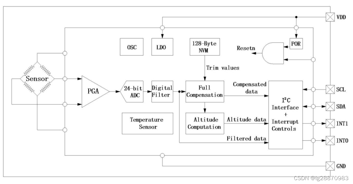
HP203B是一款超小型集高精度气压计、 高度计和温度计于一体的传感器。内部集成了24位ADC,硅传感芯片,以及存放内部参数的OTP。该传感器通过设计公司获得的专利补偿算法在传感器器件片内进行采样,信号处理以及运算,最终计算出实际的直接结果值,所以外部应用MCU只需发出信号采集命令,待完成温度压力采样后,HP203B自动计算海拔高度,单片机可以通过I²C接口直接读取压力,温度及绝对海拔高度三者的值。
每个设备都是由工厂单独校准温度和压力测量。修正的值存储在芯片上的 128 字节的非易失性内存(NVM)。在正常情况下, 用户完成没有必要做进一步校准。
3.2 HP203B技术指标

3.3 HP203B I2C总线接口命令
I2C地址
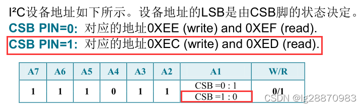
掌上实验室V8把HP203B的CSB连接了高电平。所以读写地址分别为0xED和0xEC。
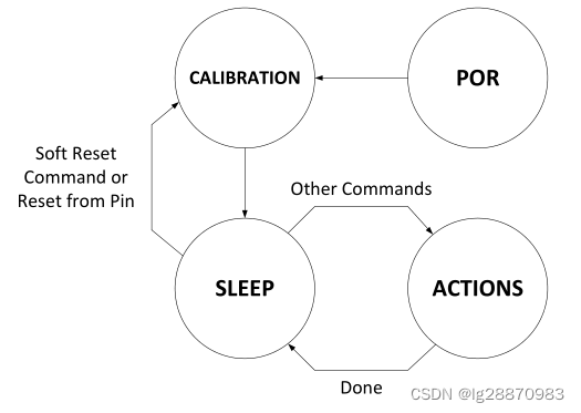
HP203B上电后先自校准,然后进入休眠模式等待指令,收到指令后执行指令,执行完毕则再次进进入休眠模式等待下一条指令。
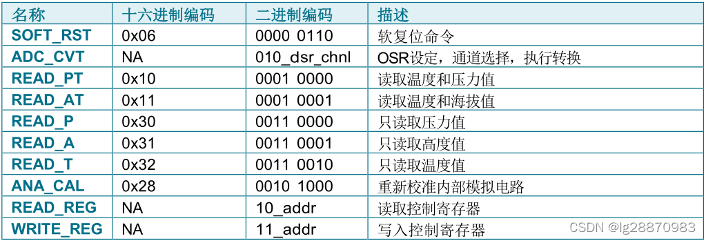
ADC_CVT转换指令
设置转换分辨率、转换通道(温度、压力或者温度+压力)并开始转换。
| bit7 | bit6 | bit5 | bit4 | bit3 | bit2 | bit1 | bit0 |
| 0 | 1 | 0 | 分辨率OSR | 通道 | |||
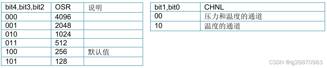
例如采用最高分辨率4096,选择压力+温度,则二进制为 010 000 00,此时 ADC_CVT=0x40。
下表是分辨率对应的转换时间,可以看到分辨率越高所需的时间越长。

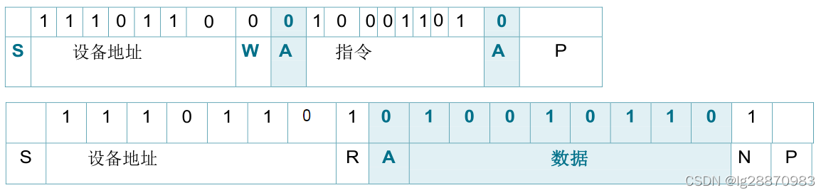
I2C主机发送指令如下,
| 设备地址 | W | ACK | 指令 | ACK | |||||||||||||||
| S | 1 | 1 | 1 | 0 | 1 | 1 | 0 | 0 | A | 0 | 1 | 0 | 0 | 0 | 0 | 0 | 0 | A | P |
其中S-起始信号,P-终止信号,A-应答信号。深色表示从机发送。
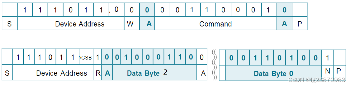
READ_P读气压值
需要分两帧发送,先发送读气压值命令0x30,然后再读3个字节气压值(高字节MSB在前)。

其中S-起始信号,P-终止信号,A-应答信号,N-非应答信号。深色表示从机发送。
气压值是由24位补码表示,最高 4 位的数据是无用,而最低有效 20 位代表气压的值。用户应当把这 20 位以 2 的补码的二进制值转换成一个整数,然后整数除以 100 获得最终结果。

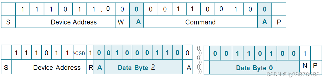
READ_A读高度值
需要分两帧发送,先发送读高度值命令0x31,然后再读3个字节高度值(高字节MSB在前)。
其中S-起始信号,P-终止信号,A-应答信号,N-非应答信号。深色表示从机发送。
高度值是由24位补码表示,最高 4 位的数据是无用,而最低有效 20 位代表高度的值。用户应当把这 20 位以 2 的补码的二进制值转换成一个整数,然后整数除以 100 获得最终结果。
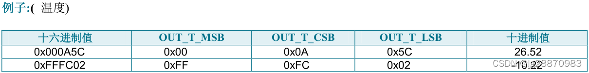
READ_T读温度值
需要分两帧发送,先发送读压力值命令0x32,然后再读3个字节温度值(高字节MSB在前)。
其中S-起始信号,P-终止信号,A-应答信号,N-非应答信号。深色表示从机发送。
温度值是由24位补码表示,最高 4 位的数据是无用,而最低有效 20 位代表温度的值。用户应当把这 20 位以 2 的补码的二进制值转换成一个整数,然后整数除以 100 获得最终结果。
- //20位补码处理
-
- int data;
-
- data &= 0xfffff; //保留20位
- if(data & 0x80000)
- data |= 0xfff00000; //扩展符号位
READ_REG读寄存器值

寄存器INT_SRC的bit5(DEV_RDY)表示处于Sleep状态(可以作为转换完成标志)。比如读取寄存器INT_SRC,命令为0x80+6位寄存器地址,即0x8D。
其中S-起始信号,P-终止信号,A-应答信号,N-非应答信号。深色表示从机发送。
4 示例代码
本例用到的驱动包有crm、gpio、misc和tmr。采用GPIO模拟I2C操作,项目包含以下几个文件
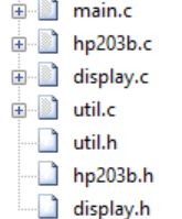
main.c
- #include "at32f403a_407_conf.h"
-
- #include "util.h"
- #include "display.h"
- #include "hp203b.h"
-
- /**
- * @brief config sclk 64 mhz with hick clock source.
- * @note the system clock is configured as follow:
- * - system clock = hick / 2 * pll_mult
- * - system clock source = pll (hick)
- * - hick = 8000000
- * - sclk = 64000000
- * - ahbdiv = 1
- * - ahbclk = 64000000
- * - apb2div = 2
- * - apb2clk = 32000000
- * - apb1div = 2
- * - apb1clk = 32000000
- * - pll_mult = 16
- * - pll_range = LE72MHZ (less equal 72 mhz)
- * @param none
- * @retval none
- */
- static void sclk_64m_hick_config(void)
- {
- /* reset crm */
- crm_reset();
-
- crm_clock_source_enable(CRM_CLOCK_SOURCE_HICK, TRUE);
-
- /* wait till hick is ready */
- while(crm_flag_get(CRM_HICK_STABLE_FLAG) != SET)
- {
- }
-
- /* config pll clock resource */
- crm_pll_config(CRM_PLL_SOURCE_HICK, CRM_PLL_MULT_16, CRM_PLL_OUTPUT_RANGE_LE72MHZ);
-
- /* enable pll */
- crm_clock_source_enable(CRM_CLOCK_SOURCE_PLL, TRUE);
-
- /* wait till pll is ready */
- while(crm_flag_get(CRM_PLL_STABLE_FLAG) != SET)
- {
- }
-
- /* config ahbclk */
- crm_ahb_div_set(CRM_AHB_DIV_1);
-
- /* config apb2clk */
- crm_apb2_div_set(CRM_APB2_DIV_2);
-
- /* config apb1clk */
- crm_apb1_div_set(CRM_APB1_DIV_2);
-
- /* enable auto step mode */
- crm_auto_step_mode_enable(TRUE);
-
- /* select pll as system clock source */
- crm_sysclk_switch(CRM_SCLK_PLL);
-
- /* wait till pll is used as system clock source */
- while(crm_sysclk_switch_status_get() != CRM_SCLK_PLL)
- {
- }
-
- /* disable auto step mode */
- crm_auto_step_mode_enable(FALSE);
-
- /* update system_core_clock global variable */
- system_core_clock_update();
- }
-
- int main(void)
- {
- static int count = 0;
- sclk_64m_hick_config();
-
- HP203B_gpio_pins_init();
- DISP_gpio_pins_init();
-
- HP203B_Reset();
- delay_ms(100);
-
-
- HP203B_StartConv();
- for(;;){
- dispaly_scan();
- if(HP203B_ReadReg(0x0d) & 0x40)
- {
- float pressure, temperature, altitude;
- HP203B_ReadData(&temperature, &pressure, &altitude);
- display_dec_int(pressure+0.5); //四舍五入显示
- HP203B_StartConv();
- }
- }
- }

util.h
- #ifndef __UTIL_H
- #define __UTIL_H
-
- void delay_us(int us);
- void delay_ms(int ms);
-
- #endif
util.c
- #include "at32f403a_407_conf.h"
-
-
- void delay_us(int us)
- {
- SysTick->LOAD = system_core_clock/1000000 * us;
- SysTick->VAL = 0;
- SysTick->CTRL = 0x5; //Systick采用系统时钟为时钟源,并启动
- while((SysTick->CTRL & (1<<16))==0);
- SysTick->CTRL = 0; //停止Systick
- }
-
- void delay_ms(int ms)
- {
- for(;ms>0;ms--)
- delay_us(1000);
- }
display.h
- #ifndef __DISPLAY_H
- #define __DISPLAY_H
-
- void DISP_gpio_pins_init(void);
-
- void display_scan();
-
- void display_dec_int(int num);
-
- #endif
display.c
- #include "at32f403a_407_conf.h"
-
- void DISP_gpio_pins_init(void)
- {
- //打开GPIO时钟
- crm_periph_clock_enable(CRM_GPIOE_PERIPH_CLOCK, TRUE);
- crm_periph_clock_enable(CRM_GPIOD_PERIPH_CLOCK, TRUE);
-
- //配置PD2~PD5, PE0~PE7为输出
- gpio_init_type gpio_init_struct;
-
- gpio_init_struct.gpio_pins = GPIO_PINS_0 | GPIO_PINS_1 | GPIO_PINS_2 | GPIO_PINS_3 | GPIO_PINS_4 | GPIO_PINS_5 | GPIO_PINS_6 | GPIO_PINS_7;
- gpio_init_struct.gpio_mode = GPIO_MODE_OUTPUT;
- gpio_init_struct.gpio_out_type = GPIO_OUTPUT_PUSH_PULL;
- gpio_init_struct.gpio_pull = GPIO_PULL_NONE;
- gpio_init_struct.gpio_drive_strength = GPIO_DRIVE_STRENGTH_STRONGER;
-
- gpio_init(GPIOE, &gpio_init_struct);
-
- gpio_init_struct.gpio_pins = GPIO_PINS_2 | GPIO_PINS_3 | GPIO_PINS_4 | GPIO_PINS_5;
- gpio_init(GPIOD, &gpio_init_struct);
- }
-
- uint8_t disp_buf[4];
- void display_dec_int(int num)
- {
- static uint8_t tab[] = {0xc0,0xf9,0xa4,0xb0,0x99,0x92,0x82,0xf8,0x80,0x90,0x88,0x83,0xc6,0xa1,0x86,0x8e};
- disp_buf[0] = tab[num/1000%10];
- disp_buf[1] = tab[num/100%10];
- disp_buf[2] = tab[num/10%10];
- disp_buf[3] = tab[num%10];
- }
-
- void display_scan()
- {
- static int cur_digit = 0;
-
- //全关
- gpio_bits_set(GPIOD, GPIO_PINS_2 | GPIO_PINS_3 | GPIO_PINS_4 | GPIO_PINS_5);
-
- //输出字形码
- gpio_bits_reset(GPIOE, 0xff); //PE0~PE7 = 0
- gpio_bits_set(GPIOE, disp_buf[cur_digit]);
-
- //打开对应位开关
- gpio_bits_reset(GPIOD, GPIO_PINS_2 << cur_digit);
-
- //更新cur_digit, 准备下一次扫描
- cur_digit = (cur_digit + 1) % 4;
- }
hp203b.h
- #ifndef __HP203B_H
- #define __HP203B_H
-
- void HP203B_gpio_pins_init(void);
-
- void HP203B_Reset(void);
- void HP203B_StartConv(void);
- unsigned char HP203B_ReadReg(unsigned char reg_addr);
- void HP203B_WriteReg(unsigned char reg_addr, unsigned char reg_val);
-
- void HP203B_ReadData(float *T, float *P, float *A);
-
- #endif
hp203b.c
- #include "at32f403a_407_conf.h"
-
- #include "util.h"
-
-
- /******************************************************************************
- I2C 基本操作
- */
- void HP203B_gpio_pins_init(void)
- {
- crm_periph_clock_enable(CRM_GPIOA_PERIPH_CLOCK, TRUE);
- crm_periph_clock_enable(CRM_GPIOC_PERIPH_CLOCK, TRUE);
-
- gpio_init_type gpio_init_struct;
- gpio_default_para_init(&gpio_init_struct);
-
- gpio_init_struct.gpio_pins
原文:https://blog.csdn.net/lg28870983/article/details/121724908
